
Introduction
A split-ring planetary gearbox is a special kind of planetary gear system which can give you a really high gear reduction ratio in a very small form factor.
In this concept specifically, we achieve a reduction of 180:1 in a gearbox that is less than a centimeter thick. That is, the motor rotates the sun gear by one full rotation in around 20 seconds and it translates to a one output gear rotation in one hour!
An overview of the concept gearbox
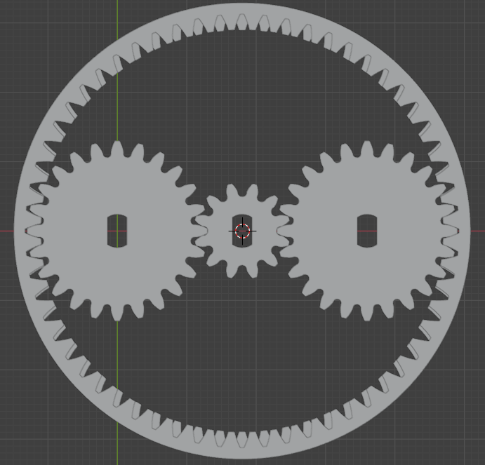
In my design shown below I have a single sun gear with 12 module-1 teeth, two planet gears with 24 module-1 teeth each, and two internal ring gears. The ring gear on the top has 60 module-1 teeth and the lower one has the same diameter but has two less teeth and isn’t technically module-1 anymore. Despite that, it meshes really well with the planet gears because given the large diameter, and small difference in teeth count, the difference in modules is very small.
Note: The module is m = d / z, where m is the module, d is the pitch circle diameter, and z is the number of teeth
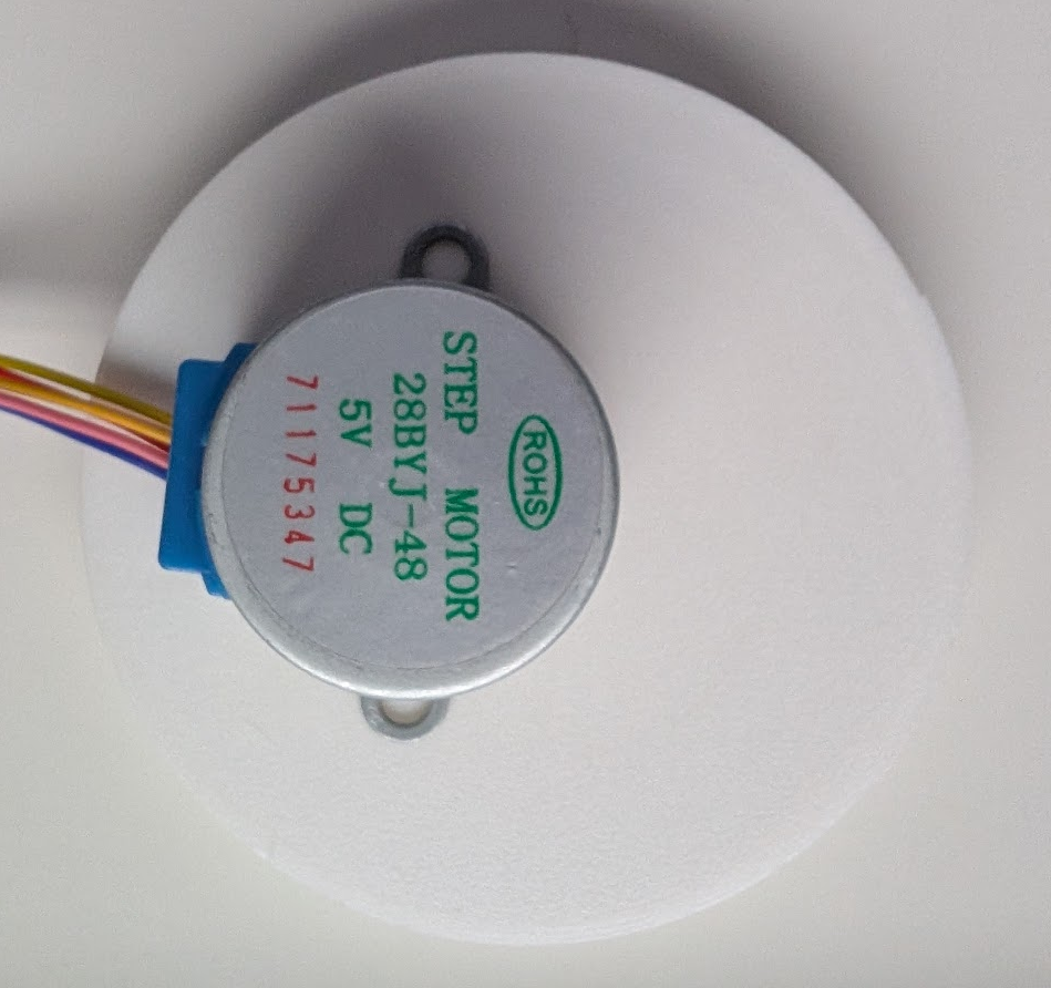
The final gearbox assembly achieves a 180:1 gear reduction ratio. This is a massive reduction. It may be a very slow speed for most applications. It is even slower motor as I am testing it with a 28BYJ-48 stepper motor. But there’s a good reason for its slow speed considering the application I have in mind for it. I want to achieve a high angular resolution for a star-tracking application. It will require slow sidereal motion (one rotation in ~24 hours). High speed is not something I need for the application.
The 28BYJ-48 motor has a 4096 step resolution in one rotation when using half-stepping. This translates to a 737,280 step resolution of the output gear. It would give me a 1.76 arcsecond resolution. One arcsecond is one-3600th of a degree, or one-1,296,000th of a full circle. My guess is, this should be a good enough resolution to not smear stars across pixels for a 135 mm lens’s field of view.
The split rings
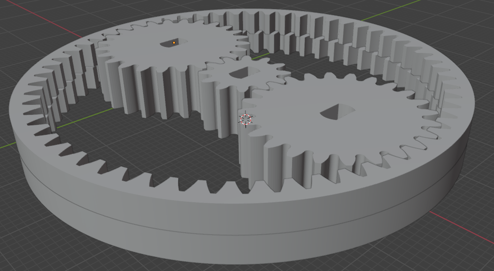
The sun and the planet gears are 8mm thick each. The split rings are 4mm thick and stacked on one another.
The split ring on top has 60 internal teeth and the one below it has 58 teeth. The ring on the bottom is fixed, while the top ring is free to move. This top ring delivers the output. As seen in the first picture, the two rings match teeth exactly at only two places. These are where the planet gears slot in.
Gear reduction
There are two gear reduction stages in this gearbox. The first one is a simple planetary gear reduction. This is a 6:1 reduction. That means, 6 rotations of the sun gear (12 teeth) equates to one rotation of a planet gear (24 teeth) around the fixed ring (60 teeth).
Stage-1 planetary reduction (i) = 1+(60/12) = 6The second stage concerns the interaction of the planet gear with split rings. Imagine when the planet gears move, they push their way in as they rotate. This causes the free top ring to move so very slightly to accommodate the planet teeth into the gap. When the planet gear rotates by 180 degrees, the ring rotates exactly by one teeth.
In the following magnified version, imagine the red teeth are fixed. The blue teeth are free to move. As the black (planet gear) pushes its teeth in, the blue gear advances ever so slightly to become meshed at the place the planet gear pushes in.
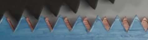
Thus by the time a planet gear moves by 360 degrees, the ring gear moves exactly by two teeth. That is 2 out of 60 teeth in 360 degrees, or 12 degrees. 30 revolutions of a planet gear moves the ring gear in one circle.
A 6:1 reduction in the first stage (sun-planet), followed by a 30:1 reduction in the second stage (planet-ring) equals to a total of 180:1 reduction from sun to ring.
Involute teeth profile calculation
I used blender to design the gears. I started by calculating the gear teeth profile equation using this tool – Internal/External Gear Calculator. Plugging in 24 for external and 60 for internal gear with a pressure angle of 20 degrees gave me the following equations.
Planet gear:
x-equation = 11.276 * (cos(u * 0.574) + u * 0.574 * sin(u * 0.574))
y-equation = 11.276 * (sin(u * 0.574) - u * 0.574 * cos(u * 0.574))
Top ring internal gear (60 teeth):
x-equation = 28.191 * (cos((0.2413 + u * 0.237)) + (0.2413 + u * 0.237) * sin((0.2413 + u * 0.237)))
y-equation = 28.191 * (sin((0.2413 + u * 0.237)) - (0.2413 + u * 0.237) * cos((0.2413 + u * 0.237)))
I used 24 and 58 to calculate the bottom gear teeth profiles. Later I simply increased gear’s diameter to match the 60 teeth gear. This changes the module slightly, but not by so much that meshing becomes an issue.
Bottom ring internal gear (58 teeth):
x-equation = 27.251 * (cos((0.2360 + u * 0.246)) + (0.2360 + u * 0.246) * sin((0.2360 + u * 0.246)))
y-equation = 27.251 * (sin((0.2360 + u * 0.246)) - (0.2360 + u * 0.246) * cos((0.2360 + u * 0.246)))
For getting the teeth profile equations for the sun gear, I used the same tool and plugged in 12 for external, 60 for internal gear and a pressure angle of 20 degrees.
Sun gear:
x-equation = 5.638 * (cos(u * 0.736) + u * 0.736 * sin(u * 0.736))
y-equation = 5.638 * (sin(u * 0.736) - u * 0.736 * cos(u * 0.736))
Modeling teeth in Blender
I followed this video tutorial to model the gears in Blender. It was good learning. By the third gear I was frustrated enough and I found an easier way. The same website has an instant calculator which spits out a python script which can be pasted in Blender to get the full profile instantly in Blender. Follow this link for the easier way – Instant Internal/External Gear Calculator. using the script in Blender is fairly easy, here is a video tutorial on how to use the script and extend the profile to a 3D gear – Instantly Modeling Internal/External Gear Pairs in Blender.
Even easier, download all of the STL files here.
3D printing the gears
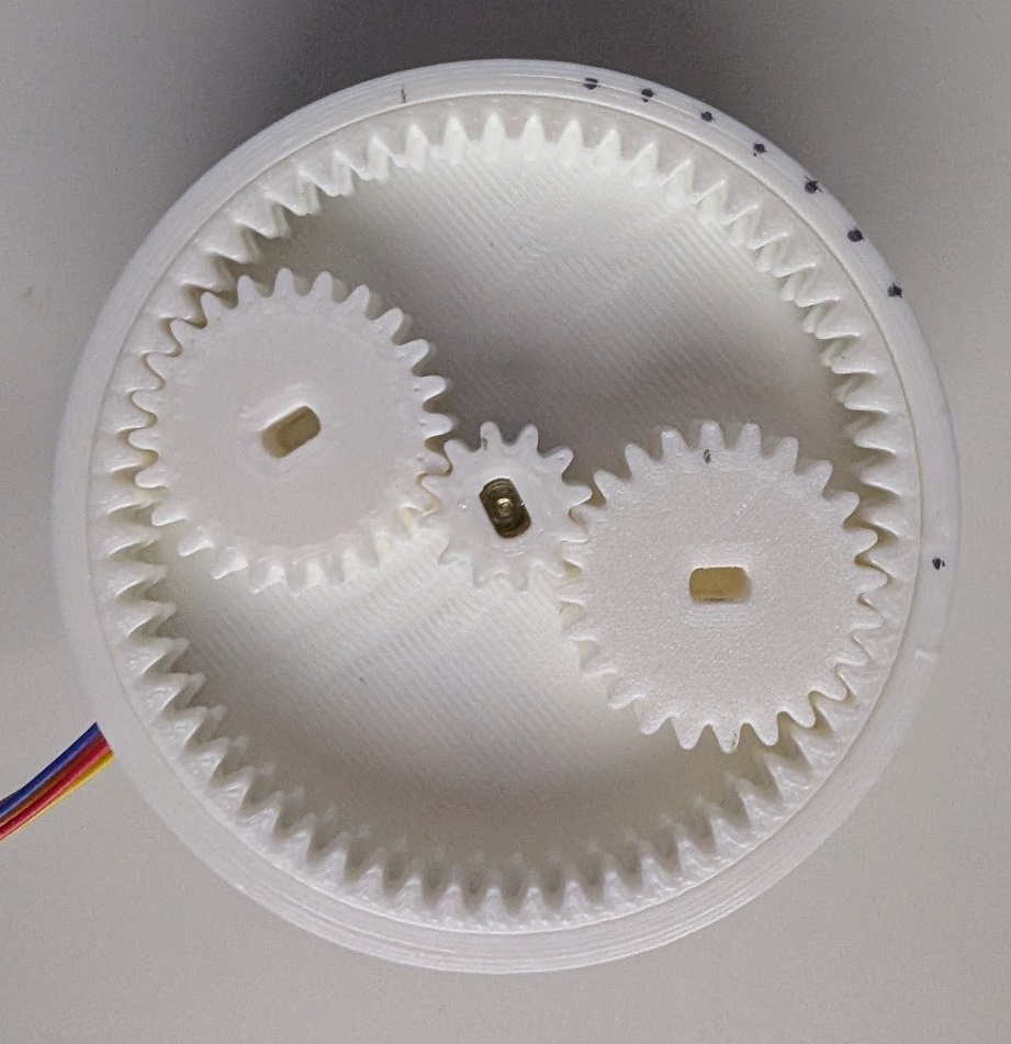
I used Ender 3 and PLA filament – 200C nozzle temperature and 50C bed temperature. I printed most of it in the best quality with 40% infill. I have figured that a horizontal expansion of -0.15mm has helped me get the perfect dimensions so that the gears mesh accurately.
The box is simply a carrier where you put in everything. I superglued the lower ring to the box. In addition I also superglued the motor to the back side with its shaft sticking inside the gearbox. Here is an image of the finished product.
Next steps
In the next blog I will go over the Arduino setup to get it all moving. At this stage the whole box is open on the top. The output ring has no output connected. It is just there to simply watch, and demonstrate the working concept.